Any object that has to be tracked is known as a unit in the Flotilla IoT fleet management system. Usually different types of vehicles are added as units to monitor them in real time. A unique identification code is assigned to every unit to separate it from others. In the ‘Units’ module, there are two modes of display including units and groups.
Units
Units includes the individual vehicles (tracking objects). All the units created by the user are displayed in the vertical list. You can also search the name of a unit to find it quickly.
Groups
Groups includes multiple number of units (vehicles). One unit can be in multiple groups. All the groups created by the users are displayed in the vertical list. You can also search the name of a group to find it quickly.
Create New Unit
You can create a new unit by adding all the required information. Following information has to be added for creating a new unit:
Required
- Name:
Give the unit any name according to your liking to distinguish it amongst all the units.
Mention the model of the tracking device attached to the unit. For configuring the device, IP address and the port is required to connect the device with the exact protocol. Multiple devices can use similar ports which means that they are following the similar protocol.
The identifier is basically the IMEI number of the tracking device and is unique for everyone. You can also identify a unit with this identifier in the Flotilla IoT software. Whenever you want to search a unit, you can enter its unique ID.
Extra
Add the phone number of the staff (driver) attached to the unit or any other concerned person.
If you want to add the unit in any group, you can search its name here.
Add the contact info related to the unit.
Add the type of unit (vehicle) in this field.
Attributes
Set a unique password for the unit.
Set the time zone according to your region.
Add the installation date of the unit.
Tags:
Set the tags of the unit to categorize it for fast searching.
Device Model:
The port and protocol of various device models can be checked from the list for adding a unit.
Create New Group
You can create a new group by adding all the required information. Following information has to be added for creating a new group:
Name
Set a unique name of the group according to your liking to distinguish it amongst all the groups.
Search Group
The parent groups can be searched and the child group can be linked to it.
Time zone
The user can set the time zone according to their location.
All Attributes (Units)
The data received from the device on different parameters is shown in this option. All the parameters showing values mean that the device is sending these types of data.
Basic:
Icon
Sensors
There are four types of sensors available in the Flotilla IoT software including:
Discreet
It is a digital sensor that gives the input in the form of true false. It is normally used to check the trueness of a condition. For example, if you add ignition sensor then you will get the result in ON/OFF.
You can enter the name with which you want to describe the sensor.
The various types of discreet sensor types are given below:
- Ignition
- Panic Button
- External Power
- Engine Status
- Car Alarm
- Doors
- Custom
The input is the attribute on which the device is sending data. Different devices have different inputs on which they send data. For example, some devices send ignition data as adc while others send it as input.
You have to set a threshold value as a parameter to check the validity of the condition. For example if the device is sending value 1 or above in ON state, you can set the threshold value as 1. It means that if the device sends value of 1 or above, the result would be ON and for value below 1, the result would be OFF.
By clicking this option, the software will consider the last value otherwise not. It is usually used when the new data value from the device is delayed so the last saved data will be considered.
Measurement
The measurement sensor is used for performing calibration on different inputs fetched from the device. At times, the device does not send data in the form that has to be displayed on the software. By applying calibration, you can display the inputs from the device in the required form. For example, if the device is sending data in the form of voltage, we can convert it into temperature, fuel consumption or any other such parameter.
It is the name that you want to set for the sensor.
It is the attribute on which device is sending a specific type of data.
It is the type of sensor that you are adding. You can also add a custom sensor type according to your requirement.
It indicates the number of the sensor that you are creating. For example, if you are creating a third fuel sensor, you will enter 3 in the index and it will display the sensor as fuel3.
Select the measurement unit for calculating the sensor value. For example, temperature can be calculated in °C and °F.
The option of relative accuracy percentage is included in the fuel sensors. If the fuel amount varies within the specified accuracy percentage, it will not be considered as drainage or fueling. It is generally set for the sensors with low precision.
- Thresholds for Drain Detection:
You can set a specified values for standard fuel consumption. If the fuel is used faster than the threshold values, it would be considered as drainage.
In this field you can set the maximum fuel consumption limit based on time after which the drainage will be considered. For example, if you set threshold at 60 units/hr and the fuel consumption is 61 units/hr, it would be considered as drainage.
In this field you can set the maximum fuel consumption limit based on distance after which the drainage will be considered. For example, if you set threshold at 10 units/km and the fuel consumption is 11 units/km, it would be considered as drainage.
- Ignore Values (Optional):
In this field, you can set a range of value to consider by providing lower and upper limits.
It is the lower limit and the values below it would be ignored. For example, if the lower limit is 0, the values below 0 will be ignored.
It is the upper limit and the values above it would be ignored. For example, if the upper limit is 100, the values above 100 will be ignored.
It is used to multiply a certain number with the raw device value for correctional purpose. In many cases, the device is sending very low data values which are not appropriate for recording keeping. So, by multiplying them with a certain number, a bigger number can be saved. For example, if the device is sending 0.001, you can multiply it by 1000 and the result will be 1 that can be saved.
By clicking this option, the software will consider the last value otherwise not. It is usually used when the new data value from the device is delayed so the last saved data will be considered.
Sensor Value
The raw data value from the device is stored here.
Quantity
The required quantity can be calculated from the raw sensor value. For example, if you are calculating the battery charging percentage and the raw data value from the device is 1 when the device is charged 25 than using this you can map other values as well.
1=25%
2=50%
3=75%
4=100%
All these values will also be shown on the graph with ‘Sensor Value’ in the x-axis and ‘Quantity’ on the y-axis.
Other Sensors
It includes the verification sensors for driver, passenger and trailers. When a unique ID is punched, it verifies that the authorized driver, passenger or trailer is attached to the unit.
You can enter the name with which you want to describe the sensor.
The driver ID can be verified by attaching this sensor.
The trailer ID can be verified by attaching this sensor.
The passenger ID can be verified by attaching this sensor.
It is the attribute on which device is sending a specific type of data.
By clicking this option, the software will consider the last value otherwise not. It is usually used when the new data value from the device is delayed so the last saved data will be considered.
Aggregate Sensors
It is used to calculate aggregate values from the input data. When the device is sending data on certain parameters, you can calculate the value of missing parameter. For example, if device is sending data speed and time then you can calculate distance from it by applying the formula distance = speed*time. You can add the inputs on which the speed and time data is being received and apply multiplication (*) operation on it to get distance value.
You can enter the name with which you want to describe the sensor.
There are many sensor types available by default along with the option to create custom sensor types. The default sensor types are given below:
- Driver ID
- Passenger ID
- Trailer UUID
- Ignition
- Panic Button
- External Power
- Engine Status
- Car Alarm
- Doors
- Fuel
- Temperature
- RPM
- Board Power
- Mileage
- Speed
- Counter
- Avg. Fuel Consumption
- Inst. Fuel Consumption
- Flow Meter
All the currently available input attributes of the selected unit are displayed in the list. By selecting the required attributes on both sides, arithmetic operations can be performed on them.
The arithmetic operation which has to be applied on the attributes can be selected from the list.
You can select the return type in which you want to display the result. There are three available options.
By clicking this option, the software will consider the last value otherwise not. It is usually used when the new data value from the device is delayed so the last saved data will be considered.
Decoder Sensors
Decoder Sensors are used to convert the data into required format. For example, converting data from Decimal to hexa decimal or binary and vice versa, you can perform all these conversions through Decoder Sensors.
Description:
Add the Description or name of the decoder sensor
Attribute:
Add any attribute for the decoder sensor that determines what type of data it is like fuel data, ignition data, etc.
Input:
Add the input on which the data is coming that has to be converted.
Value From:
Add the data format which has to be converted.
Apply First Conversion:
Select this option if the conversion is being applied for the first time.
Little Endian:
Enable this option is the data has to be stored with little endian order.
Conversion:
Select the format in which the data has to be converted.
Need Further Conversion (Optional):
Click on this option if you want to perform further conversion.
Save Last Data Received:
Check this checkbox to save the last data till the new data is received.
Mileage and Engine Hours
It contains the parameters required for calculating mileage and engine hours. There are sources available for calculating mileage, GPS, device sensor and alternative sensor. You can select any option out of them to fetch mileage value.
Mileage Accuracy %
The mileage accuracy % is the correction percentage set for the mileage received from the device. For example, if the mileage accuracy percentage is 3.5, the mileage displayed for 100km will be 103.5km. It is kept as a buffer value to compensate for the inaccuracy of the device reading.
Advance
Trip Detection:
All the parameters for trip detection are mentioned in this option.
The movement can be detected from two sources:
- GPS Speed: The movement is detected through the GPS.
- Engine Ignition Sensor: The movement is detected through engine.
- Minimal No Data Duration:
It is the minimum no data duration for ending a trip. For example, if the minimal no data duration is set 10 minutes, the trip would end if the device does not send any data for more than 10 minutes.
- Minimal Parking/Idling Duration:
It refers to the minimum stop duration of the vehicle (unit) for checking the parking and idling condition. For example, consider the case where minimal parking/idling duration is set for 5 minutes. It means that when the car is stopped for more than 5 minutes and its engine is ON, it is in idling state. Similarly, if the car is stopped for more than 5 minutes and its engine is OFF, it is in parking state.
It is the minimum movement duration of a vehicle (unit) to detect a trip. For example, if the minimal trip duration is 1 minute, it means that if a vehicle moves for more than 1 minute, it would be considered as trip otherwise not.
It is the minimum distance to be covered by a vehicle to consider it as a trip. For example, if the minimum trip distance is 100m, the trip would be detected when the vehicles covers a distance of more than 100m otherwise not.
It is the minimum speed to be achieved by a vehicle to consider it as a trip. For example, if the speed threshold is 3 km/h, the trip would be detected if the vehicle achieves speed more than 3km/h otherwise not.
Fuel Settings:
Fuel Settings option is allows you to calculate fuel consumption manually.
Standard:
The Standard setting is not for manual calculation of fuel consumption. It calculates the fuel consumption with the help of fuel sensors.
Basic:
The Basic setting allows you to set the per 100 KM fuel consumption of your vehicle. Using this info, the fuel consumption of the vehicle is calculated manually.
Advance:
The Advance setting allows more customized settings for calculating fuel consumption manually. You can add per 100 km consumption in city and highway, City Speed, Highway Speed, Fuel Consumption on Idling, etc. Using this information, much accurate fuel consumption can be calculated manually.
Fuel Filling/Drain Detection:
These are parameters that detect the filling and drainage of fuel in the software.
Minimal Fuel Filing Volume:
This is the minimal volume of fuel that has to be filled in the vehicle to be considered as a filling in the software.
Minimal Fuel Drain Volume:
This is the minimal volume of fuel drained from the tank to be considered as a drainage in the software.
Consecutive Fuel Filling Timeout:
This is the minimum time gap between two successive fillings for them to be considered as separate fillings in the software.
Consecutive Fuel Drain Timeout:
This is the minimum time gap between two successive fuel drains for them to be considered as separate drains in the software.
Detection in Motion:
By enabling this option, the fuel levels will be shown even when the fuel tank is moving.
Use Fuel Accuracy:
In case of low precision sensor, the fuel accuracy can be applied to get more consistent and accurate fuel readings.
Access
In this option, the access of the unit can be assigned to different users. A user can only give access to the users that they have created. It means that a parent account can give access to the child accounts. There are options to assign individual users and all users at once. When the access of the unit is assigned to any users, they can view, edit and delete the unit.
Notifications
In this option, notifications can be assigned to the unit. A user can assign those notifications to the unit that they have created. There are options to assign individual notifications and all at once. When a notification is assigned to the unit, it is activated for that unit.
eLogic
In this option, eLogics can be assigned to the unit. eLogic is used to convert raw inputs into desired ones. At times, the device is not sending the required inputs and by using eLogic, you can use the available inputs to get required values. Users can perform arithmetic and logical operation on different inputs to get the desired values. For example, if device is not sending distance but it is sending speed and time.
You can apply formula distance=speed*time to get distance. You can assign individual eLogics and all at once. When an eLogic is assigned to the unit, it becomes valid for that unit.
Commands
In this option, commands can be assigned to the unit. Commands are the instruction sent to the device from the software to perform a certain function. For example, if you want to turn the ignition of a vehicle OFF, you can create and assign this command. You can assign individual commands and all at once. When a command is assigned to the unit, it becomes applicable on that unit.
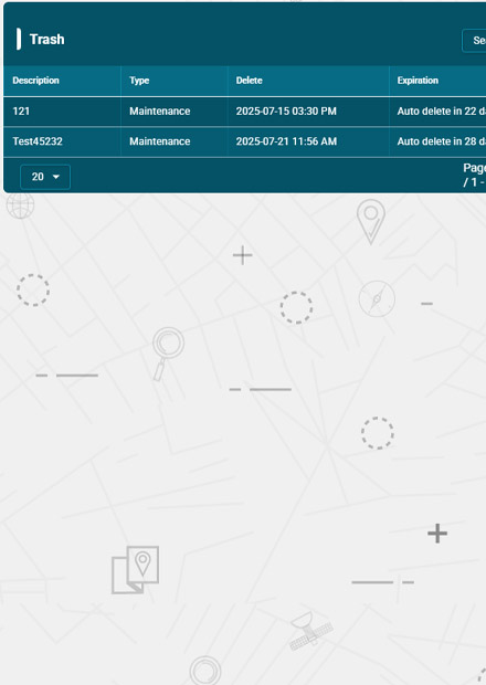
Maintenance
In this option, you can assign maintenance to the unit. Maintenance allows the users to create any maintenance needs of the vehicle and set notification alerts for them. For example, if you want to set notification based on mileage, set a threshold mileage value in ‘Start’ field and whenever the vehicle exceeds that limit, you will receive a notification alert to conduct the maintenance. You can add the distance after which you want to receive notifications in the ‘Period’ field. Users have the option to assign maintenance individually and all at once.
ECO Driving
ECO driving allows the users to monitor the driving during trips. Whether you talk about the speeding or sharp turns, everything can be monitored through ECO driving. The user can set threshold values for getting the notification alerts whenever they are crossed. For example, if the extreme acceleration is set at 0.50 G, the notification alert will be triggered whenever the vehicle exceeds this limit.